Showing posts with label quadd boolean algebra tutorials. Show all posts

Lecture 8: Postulates of Boolean Algebra

04.01.13 
Postulates of Boolean Algebra 

As we know there are three logic gates to define various logics and on the basis of same Boolean Algebra have some basic postulates (fundamental laws) as follows:

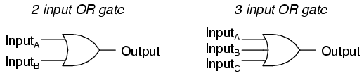
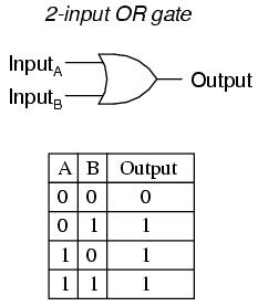
1. OR relations (which is also known as logical addition, as it has four cases: 0+0=0, 0+1=1, 1+0=1, 1+1=1)
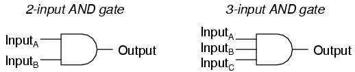
2. AND relations (which is also known as logical multiplication, as it has four cases: 0.0=0, 0.1=0, 1.0=0, 1.1=1)
3. NOT relations (which is also known as complement rule, as it has two cases: 0=1, 1=0)

Before we start, lets have a look on Principle of Duality in boolean expressions:

Principle of Duality means, that by making changes into the given boolean expression, another boolean expression can be derived. Following changes can be made to the given boolean expression:
  • Changing each OR with AND (+ with .) and its reverse (changing . with +)
  • Replacing each 0 bit with 1 bit and its reverse, replacing 1 bit with 0 bit.
For example:

0 + 0 = 0, will become, 1 . 1 = 1, after principle of duality is applied to it. And the boolean expression derived is known as DUAL OF ORIGINAL EXPRESSION. And if we see closely, 1 . 1 = 1, is also Postulate II of Boolean Algebra.

This tutorial is based on: "Computer Science - Seventh Edition" book by 'Sumita Arora' Pages: 659-660.
 
Next topic: 07.01.13: Lecture 9: Theorems of Boolean Algebra

Lecture 7: Logic Circuits (2): Converting Expressions to Logic Circuits

(Following tutorial's examples are taken from book "Computer Fundamentals - Third Edition". Author: Pradeep K Sinha and Preeti Sinha. Publisher: BPB Publications, New Delhi. Latest version of this book is available for purchase at: www.bpbonline.com)

30.06.12
Last tutorial we have seen the method of deriving Boolean expression for a given logic circuit. The reverse problem of constructing a logic circuit for a given Boolean expression is also not difficult. The three logic gates - AND, OR and NOT are said to be logically complete, because any Boolean expression may be realized using only these three gates. The method of constructing logic circuits for Boolean expressions by using only these three gates, is illustrated below with the help of few examples:

Example 1: (In book: Example 6.9 Page 79)

Construct a logic circuit for the boolean expression A.B+C
This gate is constructed using: 'Logisim'. Download this FOSS from: ozark.hendrix.edu
 The desired logic circuit is shown above, which is self-explanatory.

Example 2: (In book: Example 6.10 Page 80)

Construct a logic circuit for the Boolean Expression: A.B + C.D + E.F

This gate is constructed using: 'Logisim'. Download this FOSS from: ozark.hendrix.edu

The desired logic circuit is shown above, which is self-explanatory.

Example 3: (In book: Example 6.12 Page: 80)

Construct a logic circuit for the Boolean Expression:  
(X + Y + Z) . (X + Y) . (X + Y)

Lecture 6: Logic Circuits (1): Building Boolean Expressions


(Following tutorial's examples are taken from book "Computer Fundamentals - Third Edition". Author: Pradeep K Sinha and Preeti Sinha. Publisher: BPB Publications, New Delhi. Latest version of this book is available for purchase at: www.bpbonline.com)

29.06.12

The logic gates, described in this section, are seldom used alone, but are used in combinations. They interconnected to form gating/logic networks, which are known as combinational logic circuits. For these logic circuits, the Boolean Algebra expression can be derived by systematically progressing from input to output on the gates. Few examples are given below:

Example 1: (In book: Example 6.6, Page: 77)

Find the Boolean expression for the output of the logic circuit given below:

This gate is constructed using: 'Logisim'. Download this FOSS from: ozark.hendrix.edu
 Solution:
Input A is fed to the NOT gate, whose ouput will be A .
Inputs B and C are fed to the OD gate, whose output will be B + C.
Now two outputs ( A and  B + C) are fed as input to the AND gate. The output produced by AND gate will be A.(B+C).
Hence, D = A.(B+C), which is required Boolean expression for the output of the given logic circuit.

Example 2: (In book: Example 6.7, Page 78)

Find the Boolean expression for the output of the logic circuit given below: 

This gate is constructed using: 'Logisim'. Download this FOSS from: ozark.hendrix.edu
Solution:
The output of the OR gate is: A + B --------------- (a)
The output of the first AND gate is: A . B -------------- (b)
Since, expression (b) is fed as input to the NOT gate, the output of the NOT gate is: A.B ------------- (c)
Now, expressions (a) and (c) are fed as input to the second AND gate, whose output will be: (A + B) . (A.B)
Hence C = (A + B) . (A.B), which is the desired logic expression for the output produced by the given logic circuit. 

Lecture 5: Designing Circuits and operations and their gates (2)

28.06.12
2. OR GATE

http://sub.allaboutcircuits.com/images/04107.png
OR gate, so-called because the output of this gate will be "high" (1) if any of the inputs (first input or the second input or . . .) are "high" (1). The output of an OR gate goes "low" (0) if and only if all inputs are "low" (0). 

A two-input OR gate's truth table looks like this:
http://sub.allaboutcircuits.com/images/04108.png

3. NOT GATE
[EDITED] http://sub.allaboutcircuits.com/images/04154.png
NOT Gate is also known as Inverter, it reverses or 'invert' the input given. In digital circuits drawing its drawn as 'small circle'. That circle in the NOT-gate symbol is called an inversion bubble. A bubble on the input or output wire of another circuit symbol indicates an inversion of that signal: 0 becomes 1, and 1 becomes 0.

Some Booleen functions have identical truth tables therefore their logic circuits serves identical purposes; but one may be preferable to the other. To do this more useful logic gates are created. The following gates NAND, and NOR were created for this purpose.

4. NAND GATE
A variation on the idea of the AND gate is called the NAND gate. The word "NAND" is a verbal contraction of the words NOT and AND. Essentially, a NAND gate behaves the same as an AND gate with a NOT (inverter) gate connected to the output terminal. To symbolize this output signal inversion, the NAND gate symbol has a inversion bubble on the output line. The truth table for a NAND gate is as one might expect, exactly opposite as that of an AND gate: 

http://sub.allaboutcircuits.com/images/04106.png
As with AND gates, NAND gates are made with more than two inputs. In such cases, the same general principle applies: the output will be "low" (0) if and only if all inputs are "high" (1). If any input is "low" (0), the output will go "high" (1). 

We can see that equivalent AND gate circuit (which works same as NAND gate circuit) can be constructed with one two-input AND gate and then affixing one NOT gate on its output.

5. NOR GATE
The NOR gate is an OR gate with its output inverted, just like a NAND gate is an AND gate with an inverted output.


NOR gates, like all the other multiple-input gates seen thus far, can be manufactured with more than two inputs. Still, the same logical principle applies: the output goes "low" (0) if any of the inputs are made "high" (1). The output is "high" (1) only when all inputs are "low" (0).

We can see that equivalent OR gate circuit (which works same as NOR gate circuit) can be constructed with one two-input OR gate and then affixing one NOT gate on its output. 

  • REVIEW:
  • Rule for an AND gate: output is "high" only if first input and second input are both "high."
  • Rule for an OR gate: output is "high" if input A or input B are "high."
  • Rule for a NAND gate: output is not "high" if both the first input and the second input are "high."
  • Rule for a NOR gate: output is not "high" if either the first input or the second input are "high."
(This portion of tutorial is taken from|allaboutcircuits.com)


Lecture 4: Designing Circuits and operations and their gates (1)

26.06.12
DESIGNING CIRCUITS:

The first step in the design of a circuit is to establish a truth table that shows the output for all possible inputs.
Truth Tables
notAA'
andABA.B orABA+B

01

000
000

10

010
011

10

100
101

10

111
111

With proper input electronic digital circuits (logic circuits) establish logical manipulate paths. By passing binary signals through various combination of logic circuits, any desired information for computing can be operated on; each signal represents a binary carrying one "bit" of information.

The logic circuits or gates perform the logical operations.
(This portion of tutorial is taken from|yale.edu)

OPERATIONS AND THEIR GATES:
1. AND GATE
http://sub.allaboutcircuits.com/images/04100.png

http://sub.allaboutcircuits.com/images/04101.png
We can see, that Multiple input gates (gates with more than two inputs) exist in real world. Inverters and buffers exhaust the possibilities for single-input gate circuits. What more can be done with a single logic signal but to buffer it or invert it? To explore more logic gate possibilities, we must add more input terminals to the circuit(s). Adding more input terminals to a logic gate increases the number of input state possibilities. With a single-input gate such as the inverter or buffer, there can only be two possible input states: either the input is "high" (1) or it is "low" (0). As was mentioned previously in this chapter, a two input gate has four possibilities (00, 01, 10, and 11). A three-input gate has eight possibilities (000, 001, 010, 011, 100, 101, 110, and 111) for input states. The number of possible input states is equal to two to the power of the number of inputs: 


Lets take example of multiple input AND gate:


Now above AND gate have three inputs and applying the formula of 2n, where n is number of inputs, with three inputs it becomes: 23=8, so we will have 8 possible rows in this truth table, in the pattern of (000 (FFF), 001(FFT), 010(FTF), 011(FTT), 100(TFF), 101(TFT), 110(TTF), and 111(TTT)). In this way we can construct truth tables for multiple input gates.
...continued

Lecture 3: The conditional and the Biconditionals Statements and Binary System

25.06.12
The conditional and the Biconditionals Statements.

If the connectors \rightarrow is used between any two statements P and Q to form a compound statement P \rightarrow Q (reads if P then Q), the statement is called a conditional statement.
Example:
Let P = You Passed English
Q = You will graduate

Then this can be recorded in Truth Table as:
PQP\rightarrowQ
TTT
TFF
FTT
FFT

The statement P\rightarrowQ reads if you pass English then you will graduate. This statement is false only when you pass English (true) but you will not graduate. Therefore the final column will be true in every position but the second.

The connective \leftrightarrow is called the biconditional and may be placed between any two statements to form a compound statement P \leftrightarrow Q (reads P if and only if Q).

Then this can be recorded in Truth Table as:
PQP\leftrightarrowQ
TTT
TFF
FTF
FFT


THE BINARY SYSTEM AND BOOLEAN ALGEBRA
The Boolean algebra provides rigorous procedures for deciding whether a statement is true or false;if the statement can be expressed in two variables. In Boolean algebra true is represented by a 1 and false by a 0. With these two digits (0,1) and the three basic operations called “not”, “and” and “or”, digital algebra or switching algebra was developed.

The basic operations and their meaning:

OperationMeaningSymbol
orDetermine a single input bit from the values of two or more input+ (A+B)
andDetermines a single input bit from the value of two or more input. (A.B or AB)
notChange binary bits to its opposite value! (!A or ~A or bar over A)


Any relationship between logical variables are called logical expressions. These expressions can be written as an equation for example the equation A + B + C = F where F is the name of the output variable. The expression A + B + C = F expresses the action of and/or function. Through Boolean Algebra logical analysis can be performed using these three functions.
The electronic representation of these functions are called logic gates. There are the and gate the not and the or gates. These logic gates are basic functional units for both arithmetic and logic operations; to operate they must accept binary numbers, and should have a carry bit of one or 0, (from the adjacent lower power of two), and should produce as outputs a sum bit and a carry bit for the next higher power of two.


Lecture 2:Types of Compound statements and their connectives: Boolean Algebra for class XII Computer Science Students

24.06.12
Types of Compound statements and their connectives

1. A negation: formed when we negate a simple statement by "not"

Simple statement: Today is Thursday
Compound statement: negation: today is not Thursday

The sentence "today is not Thursday" is a compound statement called a negation.

2. When we connect two simple statements using "and" the result is a compound statement called a conjunction.
3. If the simple statements are joined by "or" the resulting compound statement is called a disjunction.
4. The If . . . then connector is used in compound statements called conditionals.
5. The if and only if connector is used to form compound statements called biconditionals.

We are familiar with using letters as replacements in algebra; in logic we can also use letters to replace statements. The common letters used to replace statements are P,Q, R: but any letters can be used.
For example:

P = Today is Saturday
Q = I passed my test

but P and Q would read Today is Saturday and I passed my test.
It is also common practice to use symbols for the connective words (or the connectors).

Connectors

Symbols
(a) not

~
(b) and

^
(c) or

(d) if . . . then

\rightarrow
(e) if and only if
\leftrightarrow
TRUTH TABLES:
Since a statement in logic is either true or false, we should be able to determine the truth or falsity of a given statement. [Logic is very precise. There should be no worry about ambiguity] Let P be a statement; then ~ P means "not P" or the negation of P. The negation of P is true whenever the statement P is false and false if P is true. These situations are confusing to write, therefore we can record these statements in a truth table.
Example: 
Let P = this is a hard course.
~P= this is not a hard course.
Then this can be recorded in Truth Table as:
P~P
TF
FT
In the first column, there are two possibilities of P; P is either True or False. Each line in the table represents a case that must be considered. In this case, there are only two cases. The truth table tells us the truth value of p in every case.
Truth Tables with the Connective ^
The Connective ^ may be placed between any two statements P and Q to form the compound statement P^Q.
Example:
Let P = Today is Monday
Q = I have a maths class
 Then this can be recorded in Truth Table as:
PQP^Q
TTT
TFF
FTF
FFF

In the compound statements, the individual statements are called components. In a compound statement with two components such as p ^ q there are four possibilities. These are called logical possibilities. The possibilities are:
1) p is true and q is true
2) p is true and q is false
3) p is false and q is true
4) p is false and q is false.
The four possibilities are covered in the four rows of the truth table. The last column gives values of P ^ Q; This is only true when both p and q are true. Using the examples given, truth tables of a more complicated nature can be built.
Let us consider the situation P∨Q
Example:
Let P = Today is Tuesday
Q = I have a maths class
Hence, P∨Q = Today is Tuesday or I have a maths class
Then this can be recorded in Truth Table as:
PQP∨Q
TTT
TFT
FTT
FFF

Like ^, here are four possibilities which are covered in the four rows of the truth table. The last column gives values of P ^ Q; This is only false when both P and Q are false.

Lecture 1: LOGIC: Boolean Algebra for class XII Computer Science Students

Date: 23.06.12

Introduction to Logic


The main ingredient in the study of logic is the principles and method used to distinguish between arguments that are valid and those that are not. Logic deals with reasoning and the ability to deduce or come to some reasonable conclusions. In everyday life we guess what is going to happen on the basis of past experiences; “It looks like its going to rain” we say meaning that it may rain today. If we wait around long enough then it may rain. This is an example of inductive reasoning
In mathematics we can discover whether or not a guess is correct by checking if our conclusions can be deduced from results already known. This is called deductive reasoning. (This portion of tutorial is taken from|yale.edu)

 Inductive Reasoning v/s Deductive Reasoning

Example of Inductive Reasoning:
All of the swans that all living beings have ever seen are white.
Therefore, all swans are white. 

This type of reasoning is based on general conceptions and tries to draw conclusions on the basis of previously laid down concepts and theories. In the above example, ALL LIVING BEINGS HAVE SEEN EVER SWANS AND FOUND THAT ALL SWANS ARE WHITE, THAT MEANS VARIOUS DIFFERENT EXAMPLES AND INSTANCES (STORIES, EVENTS) ARE BEING RECORDED IN HISTORY WHERE LIVING BEINGS HAVE SEEN WHITE SWANS. SO WE CONCLUDED OUR RESULT THAT ALL SWANS ARE WHITE.

Example of Deductive Reasoning:
All men are mortal.
Socrates is a man.
Therefore, Socrates is mortal.

This type of reasoning in contrast to inductive reasoning is not based on any general principle, rather it takes various examples and then mathematically tried to deduct accurate solutions. 'Mathematical induction' is a type of deductive reasoning, which can be easily seen in the above example, THE FIRST PREMISE STATES THAT ALL OBJECTS CLASSIFIED AS "MEN" HAVE THE ATTRIBUTE "MORTAL". THE SECOND PREMISE STATES THAT "SOCRATES" IS CLASSIFIED AS A "MAN" – A MEMBER OF THE SET "MEN". THE CONCLUSION THEN STATES THAT "SOCRATES" MUST BE "MORTAL" BECAUSE HE INHERITS THIS ATTRIBUTE FROM HIS CLASSIFICATION AS A "MAN".
(example and explanation taken from|wikipedia.org) 

Statements
The starting point of logic is a statement. A statement in the technical sense is declarative and is either true or false, but cannot be both simultaneously. In logic it is irrelevant whether a statement is true or false, the important thing is that it should be definitely one or the other. Logic statements must be either true or false.
A Statement: is a declarative sentence which is either true or false.
Examples of declarative statements:
(a) New Haven is a city in Connecticut.
(b) The month of June has thirty days.
(c) The moon is made of red cheese.
(d) Tomorrow is Saturday.
The following are not statements:
(a) Come to our party!
(b) Is your homework done?
(c) Close the door when you leave.
(d) Good by dear.
Those are not good statements because they cannot be considered true or false.
The basic type of sentence in logic is called a simple statement. A simple statement is one that has only one thought with no connecting word.
Examples of simple statements
(a) Three is a counting number.
(b) Ann is early for class
If we take a simple statement and join them with a connecting word such as and, or, if . . . then, not, if and only if, we form a new sentence called a complex or compound statement.
Compound Statements: are formed from the combination of two or more simple statements.
(a) Ann is early for class and she has her note books.

(b) Three is a counting number and is also a odd number.
(This portion of tutorial is taken from|yale.edu)