28.06.12
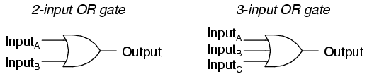
2. OR GATE
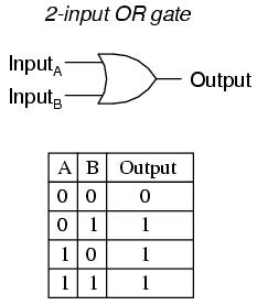
A two-input OR gate's truth table looks like this:
3. NOT GATE

2. OR GATE
 |
| http://sub.allaboutcircuits.com/images/04107.png |
OR gate, so-called because the output of this gate will be "high" (1) if any of the inputs (first input or the second input or . . .) are "high" (1). The output of an OR gate goes "low" (0) if and only if all inputs are "low" (0).
 |
| http://sub.allaboutcircuits.com/images/04108.png |
3. NOT GATE
 |
| [EDITED] http://sub.allaboutcircuits.com/images/04154.png |
NOT Gate is also known as Inverter, it reverses or 'invert' the input given. In digital circuits drawing its drawn as 'small circle'. That circle in the NOT-gate symbol is called an inversion bubble. A bubble on the input or output wire of another circuit symbol indicates an inversion of that signal: 0 becomes 1, and 1 becomes 0.
Some Booleen functions have identical
truth tables therefore their logic circuits serves identical
purposes; but one may be preferable to the other. To do this more
useful logic gates are created. The following gates NAND, and NOR
were created for this purpose.
4. NAND GATE
A variation on the idea of the AND gate
is called the NAND gate. The word "NAND" is a verbal
contraction of the words NOT and AND. Essentially, a NAND gate
behaves the same as an AND gate with a NOT (inverter) gate connected
to the output terminal. To symbolize this output signal inversion,
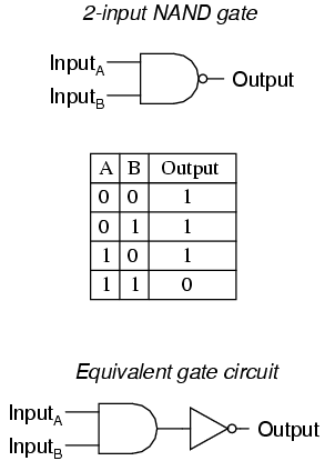
the NAND gate symbol has a inversion bubble on the output line. The truth table
for a NAND gate is as one might expect, exactly opposite as that of
an AND gate:
 |
| http://sub.allaboutcircuits.com/images/04106.png |
As with AND gates, NAND gates are made with more than two inputs. In
such cases, the same general principle applies: the output will be "low"
(0) if and only if all inputs are "high" (1). If any input is "low"
(0), the output will go "high" (1).
We can see that equivalent AND gate circuit (which works same as NAND gate circuit) can be constructed with one two-input AND gate and then affixing one NOT gate on its output.
5. NOR GATE
The NOR gate is an OR gate with its output inverted, just like a NAND gate is an AND gate with an inverted output.
NOR gates, like all the other multiple-input gates seen thus far, can be
manufactured with more than two inputs. Still, the same logical
principle applies: the output goes "low" (0) if any of the inputs are
made "high" (1). The output is "high" (1) only when all inputs are
"low" (0).
We can see that equivalent OR gate circuit (which works same as NOR
gate circuit) can be constructed with one two-input OR gate and then
affixing one NOT gate on its output.
- REVIEW:
- Rule for an AND gate: output is "high" only if first input and second input are both "high."
- Rule for an OR gate: output is "high" if input A or input B are "high."
- Rule for a NAND gate: output is not "high" if both the first input and the second input are "high."
- Rule for a NOR gate: output is not "high" if either the first input or the second input are "high."
No comments:
Post a Comment